UHV Leakvalves - Technical Specification
This specification applies to all versions of the leakvalves, manual, motor driven and pneumatically controlled.
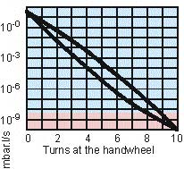
In the range of turn 0 - 3 the diaphragm
does not touch the valve seat. Due to
physical reasons, control between
10 E-9 And 10 E-10 is not possible, if
used at room temperature (red range
in the diagram). In this case the valve
is tight approx at turn 9 to 10. Control
in this range is possible if the valve
is heated.
Maximum throughput is 60 mbar.l/s
For more information
email carl@crc-technology.com
| Material housing | 316L |
| Material diaphragm | 316L, gold plated |
| Material outside of vacuum | 304, protected steel |
| Lifetime | 100,000 cycles until first service |
| Mounting position | any |
| Weights: | |
| handoperated CF 16/16 | 1.6 kg |
| handoperated CF 35/16 | 2.2 kg |
| handoperated VCR | 1.5 kg |
| motor driven | manual + 2.3 kg |
| pneumatically operated NC | manual + 8.6 kg |
| Internal pressure | Vacuum to 10 bar |
| Pressure difference | 10 bar from each side |
| Baking temperatures: | |
| Valve open | 450°C |
| Valve closed or operable | 300°C |
| Tightness housing | 1.10 E-10 mbar.l.s-1 |
| Tightness valve seat | 1.10 E-10 mbar.l.s-1 |
| Dead volumes: | |
| Main flange side | 1.0 - 1.4 cm3 |
| Side flange side | 4.6 cm3 |
| Turns of the handwheel | 10 |
| Operating time motor driven | 10 seconds for the whole range |
| Compressed air pneumatic cylinder | 4 - 9 bar overpressure |